Exposing the UART interface
UART, the serial communication interface that supports a wide range of serial protocols like RS-32, RS-422, RS-485, is not a communication protocol like SPI or I2C; rather it is a peripheral on the microcontroller. Since UART is a physical peripheral, it is likely that if we open up an IoT or embedded device we will find an UART interface somewhere on the physical circuit.
RS-232 is one of the commonly supported serial protocols in embedded and IoT devices, which is used to transfer data between two devices. RS-232 supports Full Duplex communication, which in simpler terms means the UART IC can send and receive data both at the same time. Only two devices can be connected to each other when using the RS-232 protocol.
UART Communication
UART devices using RS-232 protocol when connected together communicate directly with each other. The sender UART devices receives parallel data from a controlling device, converts it to serial data and sends it to the receiver UART device. The receiver UART device converts the serial data to parallel data and sends it to the controller on the receiver side.
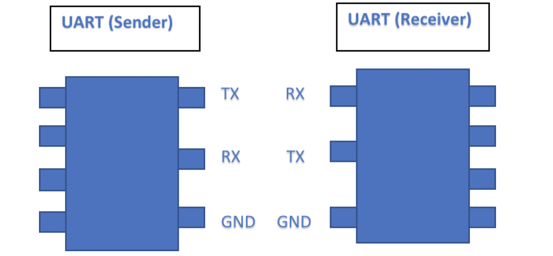
UART Circuit Connection
The minimum connection required for bi-directional communication is three.
- Transmit (TX)
- Receiver (RX)
- Ground (GND)
We can connect the TX (Sender) to RX (Receiver) and RX(Sender) to TX (Receiver) and send/receive data between the two UART devices.
IoT and Embedded Devices
IoT and Embedded devices support UART and developers use the UART interface as a debug console on the devices. It also allows users to connect to the board and view the serial console logs.
Security Concerns
Since UART interface can be used as a debugging interface on the device or to view the serial logs, it is possible for an attacker to gain shell or even root shell access to the device. Root access over UART is not too uncommon and the same steps can be followed to gain root access on potentially a lot of IoT and embedded devices available in the market today.
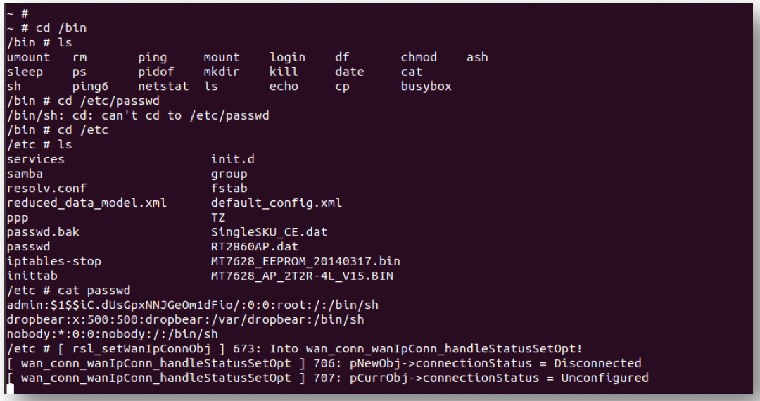
Once an attacker has access to the root shell they can download/reverse engineer the firmware, retrieve sensitive certificates or API keys stored, identify the communication protocols and potentially target devices of other users or companies.
Attack in Action - HOW TO
We identify the UART pins in an embedded device on a home router, using the following components:
- TP-Link TL-WR841N Router
- Digital/Analog Multimeter
- Attify-Badge
- Jumper Wires
- Tools to open-the-router
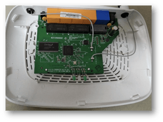
Step 1: Gaining access to the internals
Open up the TP-Link case and gain access to the internal circuit. Use the tools to open up the router.
Step 2: Making sense of the router’s internals
Identify what are the individual micro controllers and IC’s on the board.
Use google search to gain more details about your router’s internals. A good place to start looking is https://fccid.io/ and can furnish helpful information such as:
- Frequency range
- Output
- User Manual
- Internal Photos
- External Photos
Navigate to the internal photos and observe the TP Link Internal Photos: https://fccid.io/TE7WR841NXV9/Internal-Photos/TL-WR841N-Int-Photo-2192209
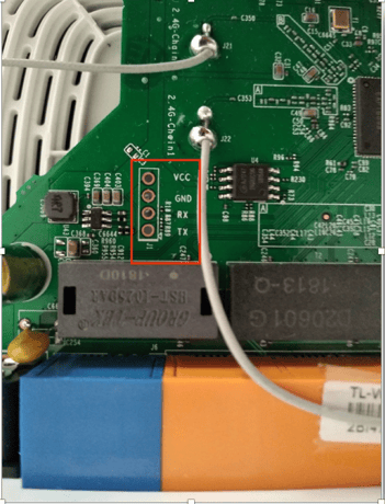
Step 3: UART Pins
If you are lucky, the UART pin names will be printed on the board. So is the case with the TP-Link router I was exploring with.
If the pins are not labelled, you can make use of tools like JTagulator to identify the UART pins. UART interfaces usually have 3 or 4 pins
- TX
- RX
- Gnd
- Vcc
Step 4: Identify the pins using a Multimeter
If, we cannot identify the UART pin names printed on the device, we can also manually identify the pins using a multimeter. UART pins are usually grouped as 3 or 4. Find a set of pins which satisfy this condition and fire up the multimeter.
- Vcc: Vcc will have a continuous high voltage during the entire the process (usually 3.3v or 5v). When a multimeter is connected to Vcc the voltage remains constant at either 3.3 or 5v.
- Transmitter (Tx): During boot up of device TX transmits large volumes of data to the connected devices. When a multimeter is connected to the TX pin there will be a huge fluctuation in voltage when the device is booting.
- Receiver (Rx): Since we are not transmitting any data to the UART interface, when a multimeter is connected to the RX pin there is a constant common voltage.
Step 5: CONNECTING TO ATTIFY BADGE
Another UART device is needed to receive and understand data received from the router. For this example, I used Attify-Badge 2.0. Connect the TP-Link and Attify badge using the pins below: .
|
TP-Link (UART) |
Attify Badge |
|
TX |
D0 |
|
RX |
D1 |
|
GND |
GND |
|
VCC |
------- |
Step 6: Identifying the BaudRate
A quick google search reveals that the baudrate for TP-Link is 115200. Or you can use https://github.com/devttys0/baudrate to identify the baudrate.
Step 7: Connecting to Computer
Connect the Attify badge to a computer using USB. Using `screen` utility connect to the USB terminal and listen on the specific baud-rate.
Now that we have identified the pins, connected to Attify badge and are listening on our computer to receive data, it’s time to power on the device.
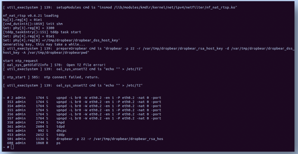
Step 8: Gaining a Root Shell
The proof is in the pudding: Observe my root-shell access to the TP-Link router.